| Name |
Symbol |
Description |
| Multiplexer |
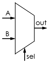 |
Selects from a number of input channels and transmits signal over a single line; selection is made based on control signal (sel) |
| Demultiplexer |
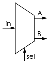 |
Transmits signal from a single input over one of a number of output channels; selection is made based on control signal (sel) |
| Flip-flop, SR (set/reset) |
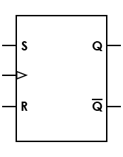 |
Basic sequential logic circuit; set (S) causes an output of 1, and reset (R) causes an output of 0 |
| Flip-flop, D (data) |
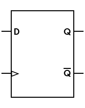 |
Output takes the value of the D (data) input, and delays it by one clock count |
| Flip-flop, D, asynchronous set/reset |
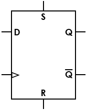 |
Set/reset (S/R) signals allow state change regardless of synchronous/clock inputs |
| Flip-flop, T (toggle) |
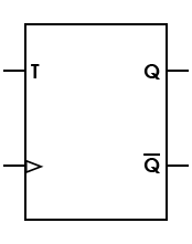 |
If the T input is high, state is changed whenever clock input is strobed; if the T input is low, the previous value is held |
| Flip-flop, JK |
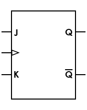 |
Universal flip-flop; can be configured to work as an SR, D, or T flip-flop |
| Flip-flop, JK, asynchronous set/reset |
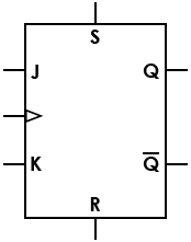 |
S/R signals allow state change regardless of synchronous/clock inputs |
| Latch, SR, asynchronous |
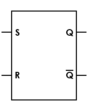 |
Relies on the states of the S and R inputs; doesn't depend on control signals |
| Latch, inverted SR, asynchronous |
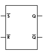 |
S and R are active low signals |
| Latch, SR, with enable |
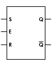 |
Enable line added; must be in high state before data can be latched |
| Latch, D, transparent |
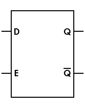 |
Called "transparent" because while the enable (E) input is active, the signal is transmitted directly from the input (D) to the output (Q) |
| Latch, D, differential |
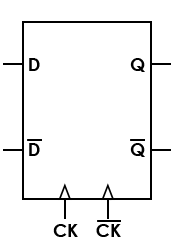 |
"Differential" refers to the data signal and its inversion |